C++ 람다 캡처는 람다식이 바깥 스코프의 변수를 값([=])이나 참조([&])로 가져오는 문법입니다. 람다를 함수 밖으로 반환하거나 저장할 때 캡처 방식을 잘못 고르면 수명이 끝난 변수를 가리키는 댕글링 참조가 생깁니다.
핵심 요약
[=]는 람다를 만들 때 변수를 복사해 두고, [&]는 원래 변수를 참조합니다. 그래서 람다를 만든 뒤 값을 바꾸면 [=] 쪽은 예전 값, [&] 쪽은 바뀐 값을 봅니다. 람다가 변수보다 오래 살면(반환, 저장, 다른 스레드로 넘기기) 참조 캡처는 댕글링이 되므로 값으로 캡처해야 합니다.
C++ 람다 캡처란 무엇입니까?
한 줄 답: C++ 람다 캡처는 람다식이 만들어내는 이름 없는 함수 객체(클로저)가 바깥 스코프의 변수를 복사본이나 참조로 붙잡아 두는 문법입니다.
cppreference의 "Lambda expressions" 문서에 따르면, 람다식은 스코프 안의 변수를 캡처할 수 있는 이름 없는 함수 객체인 클로저(closure)를 생성합니다. 대괄호로 적는 캡처 리스트는 어떤 변수를 어떤 방식으로 가져올지 지정합니다.
[]: 아무 변수도 캡처하지 않습니다.[=]: 람다 본문에서 쓰는 바깥 변수를 기본적으로 값(복사)으로 캡처합니다.[&]: 람다 본문에서 쓰는 바깥 변수를 기본적으로 참조로 캡처합니다.[x]: 변수x만 값(복사)으로 캡처합니다.[&x]: 변수x만 참조로 캡처합니다.[=, &x]: 기본적으로 값으로 복사하되,x만 참조로 캡처합니다.
컴파일러가 람다를 내부적으로 어떤 클래스로 바꾸는지는 C++ Insights란? 컴파일러가 숨겨 둔 코드(람다·range-for)를 직접 보는 법 글에서 확인할 수 있습니다.
[=]와 [&]는 무엇이 다릅니까?
한 줄 답: [=]는 람다식이 평가될 때 변수를 클로저 멤버로 복사하고, [&]는 원본 객체에 접근하는 참조를 바인딩합니다.
값으로 캡처([=] 또는 & 없는 변수 이름)하면 클로저 안에 복사본을 담는 멤버가 생기고, 람다식이 평가되는 시점에 초기화됩니다. 반면 참조로 캡처([&] 또는 &이름)하면 람다 본문이 원본 객체에 직접 접근합니다. 또한 mutable 키워드가 없으면 클로저의 operator()가 const 멤버 함수이므로 값으로 복사한 변수를 본문 안에서 수정할 수 없습니다. mutable을 붙이면 복사본을 수정할 수 있지만 원본 변수는 바뀌지 않습니다.
다음은 g++ (Debian 14.2.0-19) 14.2.0 환경에서 g++ -std=c++17 -Wall lambda_capture.cpp로 경고 없이 컴파일한 lambda_capture.cpp입니다.
#include <cstdio>
int main() {
    int x = 1;
    auto by_value = [=] { return x; };   // 만들 때 x를 복사
    auto by_ref   = [&] { return x; };   // x를 참조
    x = 42;
    std::printf("by_value=%d by_ref=%d\n", by_value(), by_ref());
    int counter = 0;
    auto inc = [counter]() mutable { return ++counter; };  // 복사본만 바뀜
    inc(); inc();
    std::printf("inc()=%d counter=%d\n", inc(), counter);
}
실행 결과는 다음과 같습니다.
by_value=1 by_ref=42
inc()=3 counter=0by_value는 람다가 만들어질 때의x값인1을 복사해 두었으므로, 이후x = 42;로 바꾸어도1을 반환합니다.by_ref는 원본x를 참조하므로 바뀐 값인42를 반환합니다.inc는[counter]() mutable로 선언되어 내부 복사본을 세 번 증가시켜3을 반환하지만, 바깥의 원본counter는 그대로0입니다.
댕글링 참조는 언제 생깁니까?
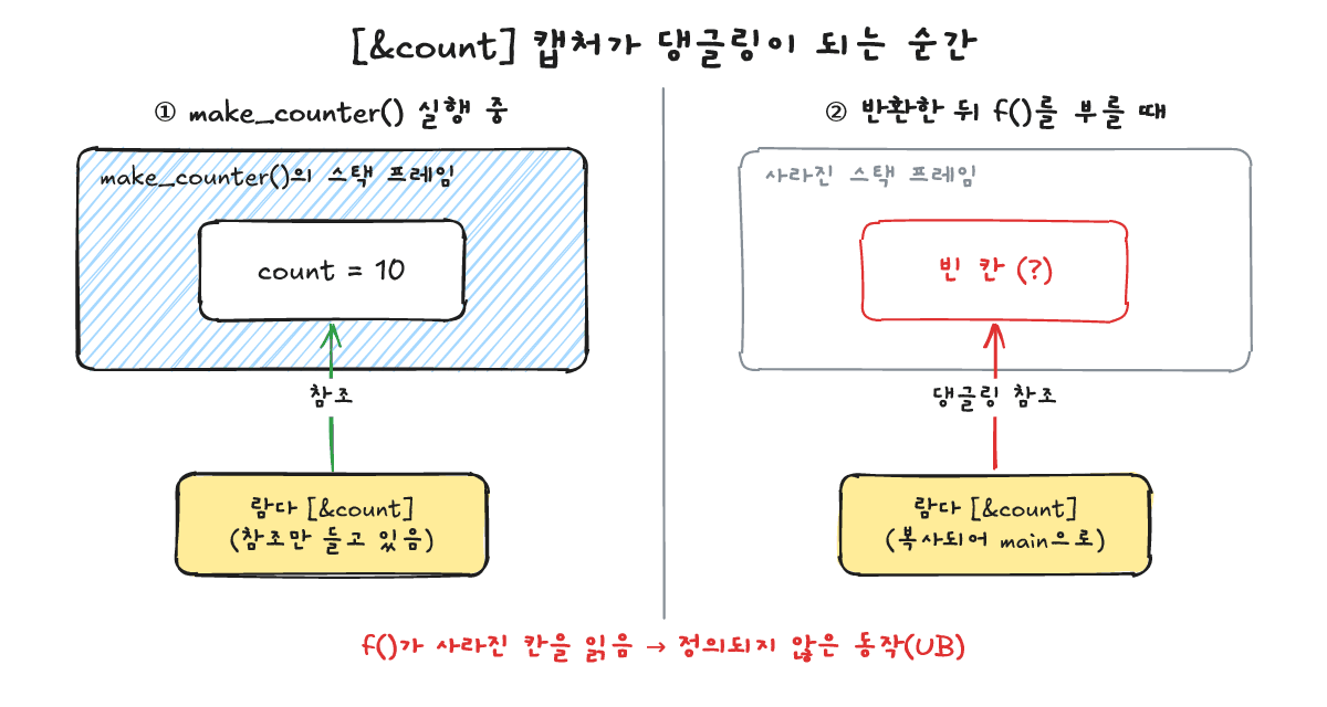
한 줄 답: 참조로 캡처한 대상의 수명이 끝난 뒤에 람다의 operator()를 호출하면 댕글링 참조가 되어 정의되지 않은 동작(UB)이 발생합니다.
cppreference에 정리된 규칙처럼, 클로저는 참조로 캡처한 객체의 수명을 연장하지 않습니다(this를 통해 캡처된 *this도 마찬가지입니다). 따라서 지역 변수를 참조로 캡처한 람다를 함수 밖으로 반환하면, 함수가 끝나는 순간 지역 변수가 사라져 참조가 빈자리를 가리키게 됩니다.
다음은 지역 변수 count를 참조로 캡처해 반환하는 lambda_dangling.cpp입니다.
#include <cstdio>
#include <functional>
std::function<int()> make_counter() {
    int count = 10;
    return [&count] { return ++count; };   // 지역 변수를 참조로 캡처 -> 함수가 끝나면 댕글링
}
int main() {
    auto f = make_counter();
    std::printf("%d\n", f());   // 정의되지 않은 동작(UB)
}
g++ -std=c++17 -Wall -Wextra -O2 lambda_dangling.cpp로 컴파일하면 다음과 같은 경고가 출력됩니다(중간의 인라인 경로 안내는 ...으로 생략했습니다).
In lambda function,
...
lambda_dangling.cpp:5:32: warning: ‘count’ is used uninitialized [-Wuninitialized]
이 실행 파일을 세 번 실행했을 때 각각 32572, 32608, 32723이 출력되었습니다(종료 코드 0). 댕글링 참조를 읽는 것은 정의되지 않은 동작입니다. 위 숫자는 이 환경에서 우연히 나온 값이며, 다른 컴파일러·옵션에서는 다른 값이 나오거나 프로그램이 죽을 수 있고, 아무 일 없이 맞는 값처럼 보일 수도 있습니다.
댕글링 캡처는 어떻게 찾고 고칩니까?
한 줄 답: AddressSanitizer(-fsanitize=address)로 실행 중 stack-use-after-return을 검출하고, 람다가 스코프보다 오래 살아남을 때는 값 캡처나 [*this]를 사용합니다.
컴파일 옵션에 AddressSanitizer, 메모리 오류를 실행 중에 찾는 법에서 다룬 -fsanitize=address를 넣고 g++ -std=c++17 -g -O0 -fsanitize=address lambda_dangling.cpp로 빌드해 실행하면, 종료 코드 1과 함께 다음과 같은 에러가 출력됩니다(실행마다 달라지는 PID와 주소는 가렸습니다).
==PID==ERROR: AddressSanitizer: stack-use-after-return on address 0x... at pc 0x... bp 0x... sp 0x...
READ of size 4 at 0x... thread T0
    #0 0x... in operator() .../lambda_dangling.cpp:5
...
SUMMARY: AddressSanitizer: stack-use-after-return .../lambda_dangling.cpp:5 in operator()
함수가 반환된 뒤 스택 메모리를 읽었다는 stack-use-after-return이 lambda_dangling.cpp:5에서 정확히 잡힙니다. 람다가 현재 스코프보다 오래 살아남는다면 참조 대신 값으로 캡처해야 합니다. 다음은 값 캡처로 고친 lambda_fixed.cpp이며, g++ -std=c++17 -Wall -Wextra로 경고 없이 컴파일됩니다.
#include <cstdio>
#include <functional>
std::function<int()> make_counter() {
    int count = 10;
    return [count]() mutable { return ++count; };   // 값으로 캡처: 람다가 복사본을 가짐
}
int main() {
    auto f = make_counter();
    std::printf("%d\n", f());
    std::printf("%d\n", f());
}
실행 결과는 다음과 같습니다.
11
12
실무에서 기억해 둘 기준은 두 가지입니다. 첫째, 람다를 반환하거나 컨테이너·콜백·다른 스레드로 넘겨 스코프 밖에서 실행한다면 값으로 캡처합니다. 둘째, 클래스 멤버 함수 안에서 멤버 변수에 접근할 때는 this를 거치는데, [=]를 쓰면 객체 자체가 복사되는 것이 아니라 this 포인터가 복사되어 결과적으로 *this가 참조로 암묵 캡처됩니다([=]를 통한 this 암묵 캡처는 C++20부터 비권장입니다). 객체가 먼저 소멸할 수 있다면 C++17에 도입된 [*this]를 사용해 객체 전체를 복사본으로 캡처합니다.
자주 묻는 질문은 무엇입니까?
한 줄 답: 이동 캡처 문법(C++14), [=] 사용 시 포인터와 this 주의점, 스마트 포인터 캡처의 수명 규칙을 정리합니다.
이동 캡처는 어떻게 합니까?
C++14부터 도입된 초기화 캡처(init capture) 문법인 [v = std::move(v)]를 사용하면 복사할 수 없는 이동 전용(move-only) 타입도 람다 안으로 이동시킬 수 있습니다(위 한 줄 문법 예시는 별도로 실행하지 않은 코드 조각입니다). 복사와 이동의 차이는 복사 생성자 vs 이동 생성자 차이: 언제 무엇이 호출되나? 글을 참고하시기 바랍니다.
[=]만 쓰면 항상 안전합니까?
항상 안전하지는 않습니다. 포인터 변수를 값으로 캡처하면 주소값만 복사되므로 가리키던 대상이 먼저 소멸하면 여전히 댕글링 포인터가 되며, 멤버 함수 안에서는 [=]가 this 포인터만 복사하므로 객체 수명이 끝나면 *this 접근이 정의되지 않은 동작이 됩니다.
스마트 포인터를 캡처하면 어떻습니까?
std::shared_ptr를 값으로 복사해 캡처하면 클로저가 살아 있는 동안 참조 카운트가 유지되어 대상 객체의 수명도 함께 유지됩니다(C++ unique_ptr와 shared_ptr, 면접에서 고르는 기준 참고).
함께 보면 좋은 글은 무엇입니까?
한 줄 답: 람다의 클래스 변환, AddressSanitizer 사용법, 스마트 포인터, 복사·이동 생성자를 다룬 글입니다.
- C++ Insights란? 컴파일러가 숨겨 둔 코드(람다·range-for)를 직접 보는 법
- AddressSanitizer, 메모리 오류를 실행 중에 찾는 법
- C++ unique_ptr와 shared_ptr, 면접에서 고르는 기준
- 복사 생성자 vs 이동 생성자 차이: 언제 무엇이 호출되나?
출처는 어디입니까?
한 줄 답: cppreference의 Lambda expressions 문서와 GCC 14.2.0 실측 환경입니다.
- cppreference.com, "Lambda expressions" (확인 2026-10-25)
- 컴파일 및 실행 환경:
g++ (Debian 14.2.0-19) 14.2.0,x86_64(확인 2026-10-25)
C++ lambda capture is the syntax that lets a lambda expression bring outer-scope variables into its body either by copy ([=]) or by reference ([&]). Choosing the wrong capture mode when returning or storing a lambda can leave a dangling reference to a variable whose lifetime has already ended.
Summary
[=] copies captured variables when the lambda is created, while [&] references the original variables. If you modify a variable after creating the lambda, [=] sees the old value and [&] sees the updated value. Whenever a lambda outlives the variable (returned from a function, stored, or passed to another thread), reference capture dangles, so you should capture by value.
What is C++ lambda capture?
One-line answer: C++ lambda capture is the syntax that lets the unnamed function object (closure) created by a lambda expression hold outer-scope variables by copy or by reference.
According to the cppreference "Lambda expressions" documentation, a lambda expression creates a closure: an unnamed function object that can capture variables in scope. The capture list inside square brackets specifies which variables are captured and how.
[]: captures nothing.[=]: captures outer variables used in the lambda body by copy by default.[&]: captures outer variables used in the lambda body by reference by default.[x]: captures onlyxby copy.[&x]: captures onlyxby reference.[=, &x]: captures by copy by default, but capturesxby reference.
To see how the compiler turns a lambda into a class under the hood, check How C++ Insights reveals compiler-generated code for lambdas and range-for (Korean).
What is the difference between [=] and [&]?
One-line answer: [=] initializes closure members with copies when the lambda expression is evaluated, whereas [&] accesses the original object by reference.
When captured by copy ([=] or variable names without &), the closure holds member copies initialized at the moment the lambda expression is evaluated. When captured by reference ([&] or &name), the lambda body accesses the original object directly. Without mutable, the closure's operator() is const, so copies captured by value cannot be modified inside the body; adding mutable allows modifying those copies while leaving the original variable unchanged.
Here is lambda_capture.cpp, compiled without warnings using g++ -std=c++17 -Wall lambda_capture.cpp on g++ (Debian 14.2.0-19) 14.2.0 (the inline comments copy x on creation, reference x, and modify only the copy).
#include <cstdio>
int main() {
    int x = 1;
    auto by_value = [=] { return x; };   // 만들 때 x를 복사
    auto by_ref   = [&] { return x; };   // x를 참조
    x = 42;
    std::printf("by_value=%d by_ref=%d\n", by_value(), by_ref());
    int counter = 0;
    auto inc = [counter]() mutable { return ++counter; };  // 복사본만 바뀜
    inc(); inc();
    std::printf("inc()=%d counter=%d\n", inc(), counter);
}
Running the program prints:
by_value=1 by_ref=42
inc()=3 counter=0by_valuecopiedxwhen the lambda was created (1), so assigningx = 42;later does not change its return value of1.by_refrefers to the originalx, so it returns the updated value42.incis markedmutable, so calling it three times increments its internal copy to3while the outercounterremains0.
When does a dangling reference occur?
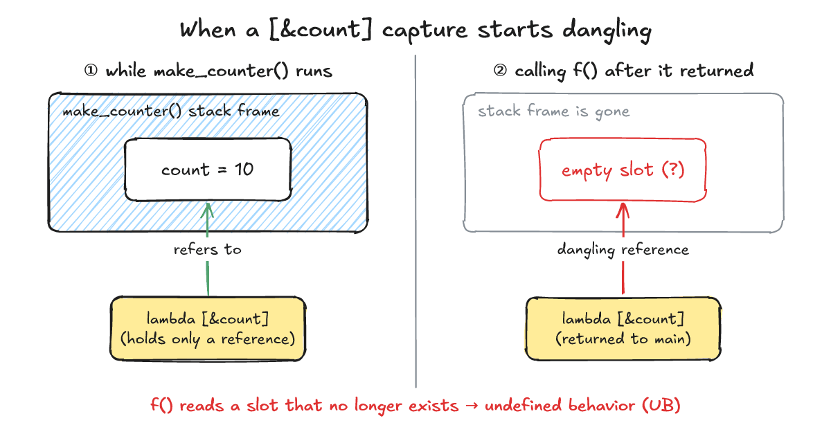
One-line answer: If an entity is captured by reference and operator() is called after that entity's lifetime has ended, the reference dangles and triggers undefined behavior (UB).
As documented on cppreference, closures do not extend the lifetime of objects captured by reference, and the same rule applies to *this captured via this. Returning a lambda that captured a local variable by reference means the local variable is destroyed when the function returns, leaving the closure with a dangling reference.
Below is lambda_dangling.cpp, which captures the local variable count by reference and returns the lambda (resulting in a dangling reference after the function returns, and undefined behavior when called).
#include <cstdio>
#include <functional>
std::function<int()> make_counter() {
    int count = 10;
    return [&count] { return ++count; };   // 지역 변수를 참조로 캡처 -> 함수가 끝나면 댕글링
}
int main() {
    auto f = make_counter();
    std::printf("%d\n", f());   // 정의되지 않은 동작(UB)
}
Compiling with g++ -std=c++17 -Wall -Wextra -O2 lambda_dangling.cpp prints the following warning excerpt (with ... representing omitted inlining notes):
In lambda function,
...
lambda_dangling.cpp:5:32: warning: ‘count’ is used uninitialized [-Wuninitialized]
Three runs printed 32572, 32608, and 32723 (exit 0). Reading a dangling reference is undefined behavior. The numbers above happened to come out in this environment; with another compiler or other options you may get different values or a crash, or it may even look like it works and prints the right value.
How do you detect and fix a dangling capture?
One-line answer: Use AddressSanitizer (-fsanitize=address) to catch stack-use-after-return at runtime, and capture by value or with [*this] whenever a lambda outlives its scope.
Building with AddressSanitizer: finding memory errors at runtime (Korean) via g++ -std=c++17 -g -O0 -fsanitize=address lambda_dangling.cpp and running the binary exits with code 1 and prints the following report (PID and addresses masked):
==PID==ERROR: AddressSanitizer: stack-use-after-return on address 0x... at pc 0x... bp 0x... sp 0x...
READ of size 4 at 0x... thread T0
    #0 0x... in operator() .../lambda_dangling.cpp:5
...
SUMMARY: AddressSanitizer: stack-use-after-return .../lambda_dangling.cpp:5 in operator()
AddressSanitizer pinpoints the stack-use-after-return at lambda_dangling.cpp:5. To fix it, capture by value so the closure owns its own copy. Here is lambda_fixed.cpp, which compiles without warnings under g++ -std=c++17 -Wall -Wextra (capturing by value so the lambda holds a copy).
#include <cstdio>
#include <functional>
std::function<int()> make_counter() {
    int count = 10;
    return [count]() mutable { return ++count; };   // 값으로 캡처: 람다가 복사본을 가짐
}
int main() {
    auto f = make_counter();
    std::printf("%d\n", f());
    std::printf("%d\n", f());
}
The output is:
11
12
Two practical rules help prevent dangling captures. First, capture by value whenever the lambda outlives the current scope (such as when returning it, storing it in a container or callback, or passing it to another thread). Second, inside a member function, members are accessed through this: writing [=] implicitly captures *this by reference by copying the this pointer rather than copying the object itself (implicit capture of this via [=] is deprecated since C++20). Use [*this] (introduced in C++17) to capture a copy of the object.
What are the frequently asked questions?
One-line answer: Here are answers on C++14 init capture for move-only types, why [=] can still dangle with pointers or this, and capturing smart pointers.
How do you move-capture an object into a lambda?
Use C++14 init capture such as [v = std::move(v)] to capture move-only types (this one-line syntax snippet is not a separately run program). For the difference between copying and moving, see Copy constructor vs move constructor: when each is called (Korean).
Is capturing with [=] always safe from dangling?
No. If you capture a raw pointer by copy, only the pointer value is copied, so it still dangles if the pointee is destroyed; likewise, inside a member function, [=] copies the this pointer rather than the object, so *this dangles if the object's lifetime ends.
What happens when you capture a smart pointer?
Copying a std::shared_ptr into a lambda keeps the reference count and the managed object alive for as long as the closure exists (see How to choose between C++ unique_ptr and shared_ptr (Korean)).
What related posts are worth reading?
One-line answer: Related posts covering C++ Insights, AddressSanitizer, smart pointers, and copy vs move constructors.
- What is C++ Insights? Seeing compiler-generated code for lambdas and range-for (Korean)
- AddressSanitizer: how to find memory errors at runtime (Korean)
- C++ unique_ptr vs shared_ptr: criteria for choosing (Korean)
- Copy constructor vs move constructor: when each is called (Korean)
What are the sources?
One-line answer: The cppreference Lambda expressions documentation and our GCC 14.2.0 test environment.
- cppreference.com, "Lambda expressions" (checked 2026-10-25)
- Compiler and environment:
g++ (Debian 14.2.0-19) 14.2.0,x86_64(checked 2026-10-25)